

close
Choose Your Site
Global
Social Media


| Quantity: | |
|---|---|


Customized
MingHeng
Internal Structure
Performance Behavior
Vertical Load Bearing: With steel plates restraining rubber bulging, the bearing pad achieves high vertical capacity within relatively modest thickness. Compression deformation remains controllable within the design load range.
Horizontal Displacement: Rubber layers deform under shear force with relatively low horizontal stiffness, producing small reaction forces on piers during beam movement.
Rotational Accommodation: When beam ends rotate due to loads or installation slope, rubber layers adjust contact through non uniform compression, reducing localized stress concentration.
Sliding Resistance Reduction: The friction coefficient of the PTFE sliding surface is lower than direct rubber to concrete contact, with greater advantages under large displacement.
Durability Protection: The outer rubber fully encapsulates steel plates. Chloroprene rubber performs stably in coastal and high UV environments.
How to Select
When selecting a laminated rubber bearing pad, first confirm the planar shape required by the bridge structure. Rectangular shapes suit most concrete beams with flat soffits, while circular shapes suit circular pier columns or locations where direction is not critical. Then confirm displacement requirements. If the bridge span is large or the region has significant temperature variation, PTFE sliding configuration should be considered.
For dimensions, planar size is determined by design load and local concrete compressive strength, while thickness is determined by horizontal displacement and rotational requirements. For rubber material, natural rubber is sufficient for conventional inland areas, while chloroprene rubber is recommended for coastal or high UV regions. Steel plate layers are determined by vertical load requirements. Increasing layers improves stiffness but also adds weight and cost.
Custom Production
All laminated rubber bearing pads are produced according to project requirements. Customization requires confirmation of planar shape, dimensions, rubber material, steel plate layers, and surface configuration. Rectangular products require length and width, while circular products require diameter.
Engineering Applications
Beam end support for small to medium span highway bridges
Pier to girder connection nodes in urban viaducts and ramp bridges
Beam end support locations in railway bridges
Beam ends with larger displacement requirements in long span continuous girder bridges
Bridge joint locations in regions with significant temperature variation
Custom matching for bearing replacement projects on existing bridges
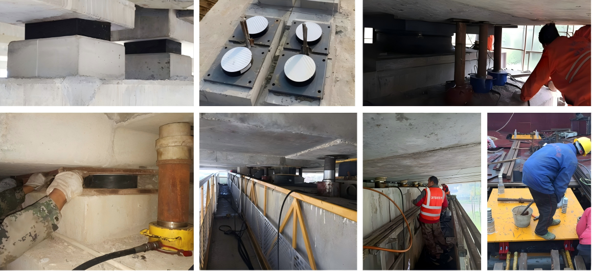
Before installation, check the flatness of the pad stone surface and remove dust and oil. Align the bearing pad centerline with the design position during placement to avoid eccentricity. PTFE sliding surfaces should remain clean, and stainless steel plates should be free of scratches or debris. Lower the beam slowly to avoid impact. After completion, check for void or eccentric compression. Routine inspection focuses on abnormal deformation, cracks, or steel plate exposure.


